Pcb Mouse Bites Dimensions
When youâ re finished click done.
Pcb mouse bites dimensions. Tab routing panelization with mouse bite holes. In fact mouse bites may be directly added to the pcb using hole via primitives and not feature on the schematics at. If desired click on the opposite edge of the pcb to insert a matching mouse bite on the opposed edge of the pcb. Schematic symbol there is no standardised symbol for mouse bites.
Pcb arrays that can t feasibly use a v cut method will instead use a tab routing method. I want to panelize them. It can rotate and take a bite out of the good part of the board. It does make it tougher.
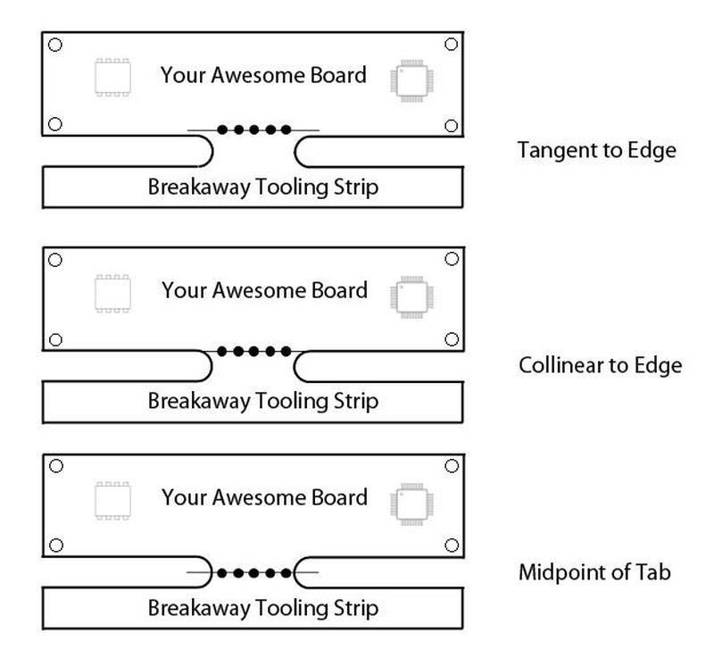
With this method pcbs are pre cut from the array and held in place on the board with perforated tabs. Overview mouse bites are a set of drill holes arranged in a small semi circle on the edge of the board. I ve created two independent circuit layouts in proteus ares. Rat bite pcb depanel machine rat bite pcb router desktop pcb router sally way.
You should design your pcb array to secure the benefits of running multiple boards through your processes. With the four sets of mouse bite joints all around the circular pcb you will not be able to bend and break it away. Sometimes this is done with a final separation router pass after assembly i do this with another intricate design that requires mechanical accuracy and smooth edges. The mouse bites for your entire array will be quickly generated and inserted into your panel.
Click start again if you want to insert additional mouse bites. Assume the largest x dimension will be 7 8 and the largest y dimension will be 10 8. An array is combining a single pcb multiple times to make a larger array of connected boards. Automatic mouse bites or break away tabs for pcbs with dex pcb duration.
Board houses won t usually combine tab and score but they can be very handy to specify. They are used when the board is going to be panelised routed and populated with a pick and place machine. I like to use these when a smooth board edge is desired and where low breakaway force is desirable or where a separator tool can t get access e g under connectors that overhang the board edge. I ve figured out how to panelize the two pcb layouts on one board using the ares gerber viewer but i m stumped on how to add slots and or mouse bites so the boards can be separated after i receive them from the fab house.
3 to 5 mouse bites holes are used in these perforation patterns.
